4.8 KiB
4.8 KiB
4-Bit Arithmetic Logic Unit (ALU) & 8-Bit Multiplication
- This project was originally designed for TTL-based implementation but was estimated to require approximately 100 TTL chips.
- Consequently, it is now being revisited for FPGA implementation using the Tang Primer 20k. The circuit also includes a 7-segment display and a 4511 TTL chip for BCD-to-7SD encoding.
- Additionally, old and unused Verilog and Logisim files are being included in the repository.
- Gowin Education v1.9.9.03 & Logisim Evolution v3.9.0
Circuit Design
- All bits are unsigned.
- The circuit uses an 8-input DIP switch for A and B, a 3-input opcode selector, and a 1-bit CarryIn/BorrowIn input (depending on the opcode).
- The BCD module employs a double dabble algorithm, but the 3rd and 4th bits in the 100s position are not enabled. As a result, the integer "400" cannot be displayed on the 7-segment display.
- The opcode uses a 3-bit decoder with one-hot encoding for selection.
- CarryOut/BorrowOut and Overflow are displayed using LEDs.
Inputs:
- 2-Bit Selector: Determines which data is displayed on the screen.
- 3-Bit OpCode: Specifies the operation to be performed.
- 4-Bit Input A: The first operand.
- 4-Bit Input B: The second operand.
- 1-Bit CarryIn/BorrowIn: Input carry for arithmetic operations.
Outputs:
- 11-Bit Result: The ALU converts the binary result to BCD. This feature can be easily disabled if binary output is preferred.
- 1-Bit CarryOut/BorrowOut: Indicates carry or borrow in arithmetic operations.
- 1-Bit Overflow: Indicates an overflow condition during addition.
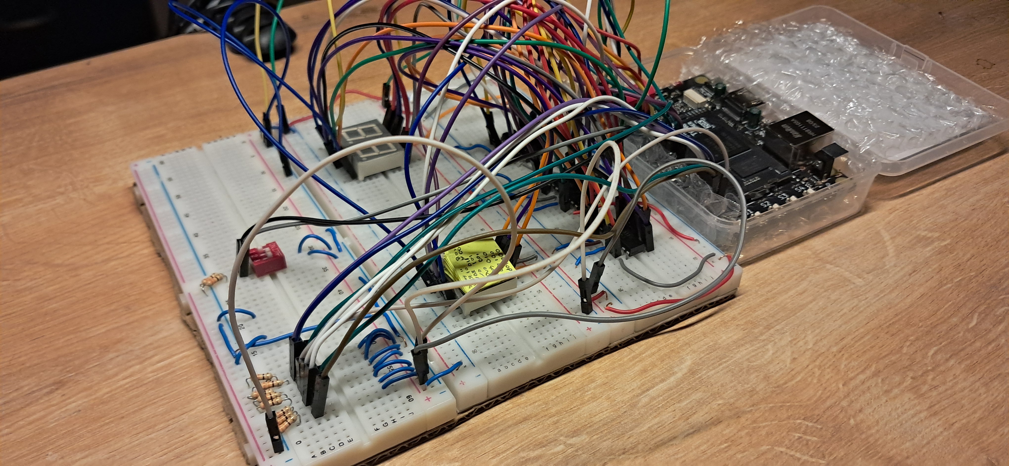
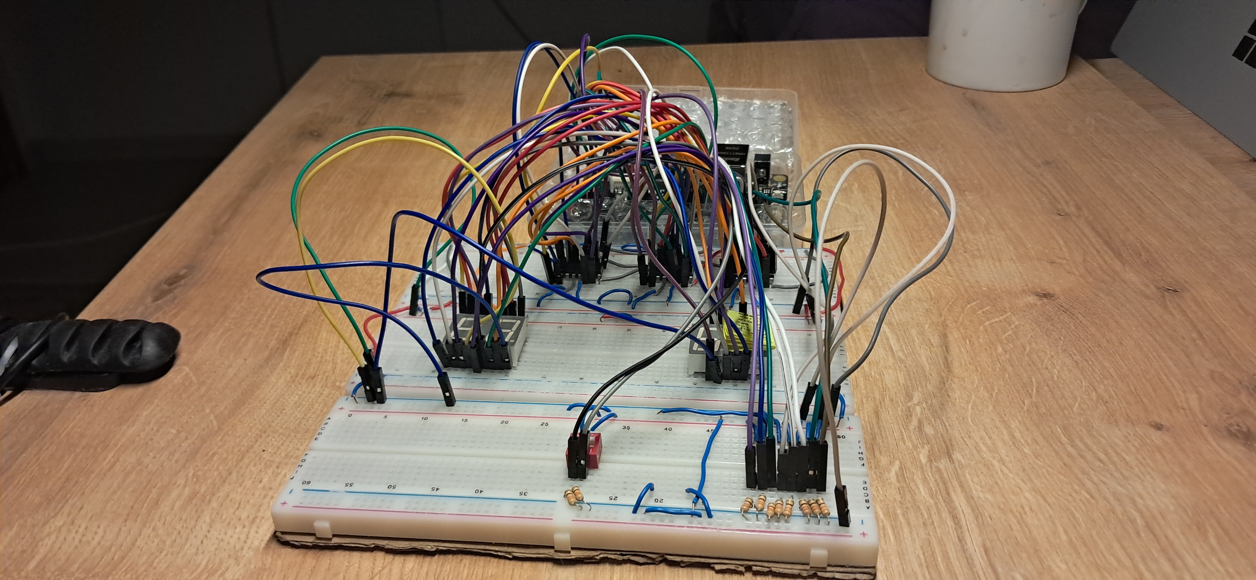
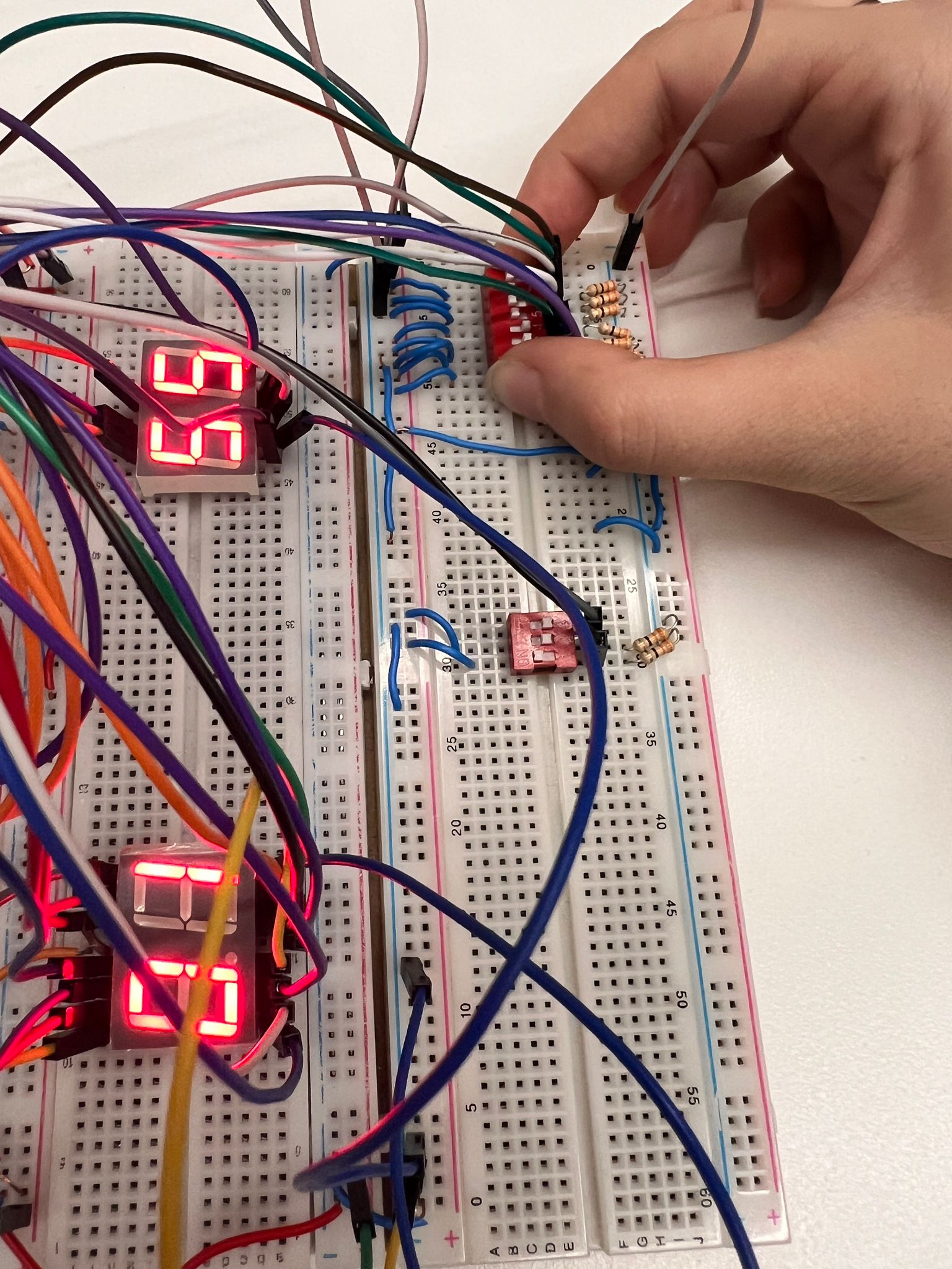
Preview
Click to expand and view media of the real-life circuit.
opCode
A&B Input
A input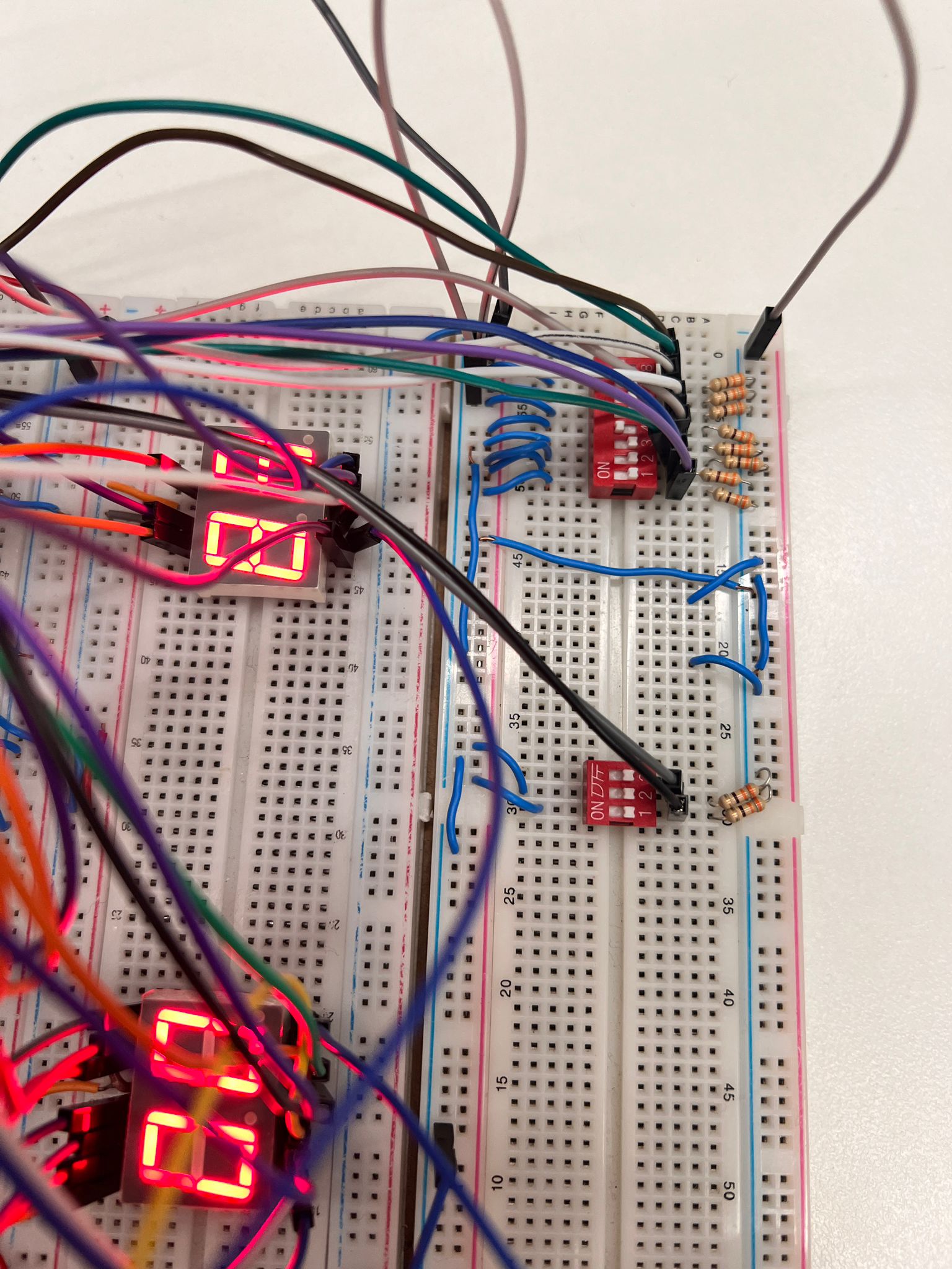 B input
Logic Unit
AND Gate
OR Gate
XOR Gate
Arithmetic Unit
Addition & Addition with CarryIN
Addition & Overflow and CarryOut led
Subtraction & BorrowOut Led
8-2 with Borrow In
Multiplication
Screen Selector Table
The 2-bit screen selector determines what is displayed on the screen:
| Screen Selector | Displayed Data |
|---|---|
| 00 | Input A |
| 01 | Input B |
| 10 | opCode |
| 11 | Result |
Opcode Table
The table below describes the operations performed by the ALU based on the 3-bit opcode:
| Opcode | Operation | Result Bits | Carry/Borrow In/Out Usage |
|---|---|---|---|
| 000 | Addition | 4 | ✅ |
| 001 | Subtraction | 4 | ✅ |
| 010 | Multiplication | 8 | ❌ |
| 100 | AND | 4 | ❌ |
| 101 | OR | 4 | ❌ |
| 110 | XOR | 4 | ❌ |
| 011 | ❌ | ❌ | ❌ |
| 111 | ❌ | ❌ | ❌ |
Important NOTE!
You are free to use this repository as you wish, but please note that I am not actively maintaining it. This repository was created for a specific project, and I would like to preserve the original code.
Credit
- BUR4KBEY: Honorable mention for resolving DIP switch assignments in the FloorPlanner(Gowin). Also for this readme template.